|
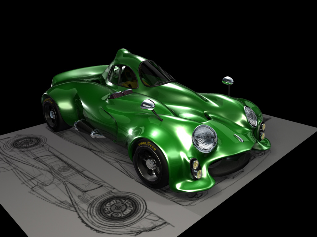
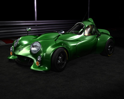
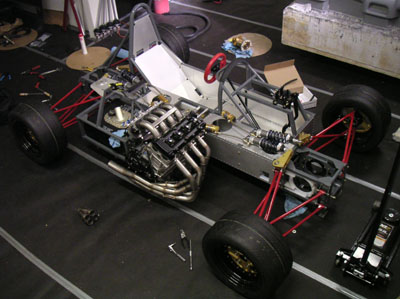
09/30/05 The exhaust is being corrected. In the meantime I'm tracking down (and having made) a number of miscellaneous fasteners, spacers, etc. The glamorous stuff. So while all that is taking place, I got an offer from Ian Wilmoth to do another styling exercise that would be different from my bodywork but fit the mechaincals. So I sent off the pertinent CAD files and in a few days Ian produced this (click each pic for larger version):
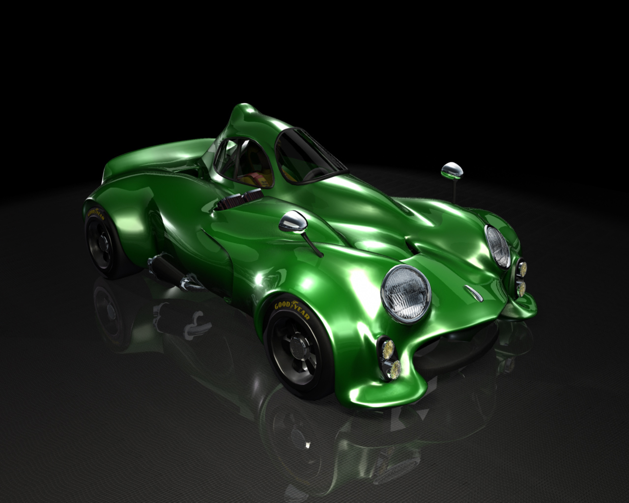
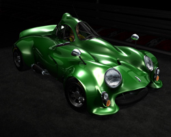
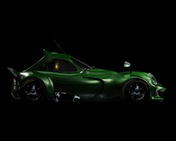
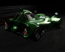
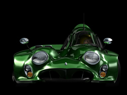
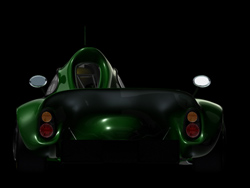
This is great stuff. It's definitely different from my approach, very organic and creature-like. It hides the car's near-square proportions and is bizarre and funky enough to be way cool. I am also a fan of closed-cockpit cars... Who knows, once the basics are taken care of and I have a running, manufactureable chassis, something along these lines could be pursued as an alternative body. And it would have to be green. Many thanks to Ian for the effort! 10/05/05 An update from Ian (in the absense of any of my own, although work does continue and progress is being made). Here are some different views of the "superfrog" body design. See here for bigger pics. I like it! :)
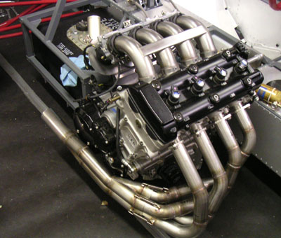
This is actually very timely, since I'm currently contemplating the changes that will need to be made for production. I now realise that the underbody aero package will need to be contained within the chassis footprint, so as to enable variants such as this one while retaining the important pieces. It's a new line of thinking for how the chassis, the floor and the bodywork will be eventually built and put together. Combine that with the wide variety of powerplants I want to accommodate (including the V8) and their attendant exhaust routing demands and I'll have my hands full for a while. I've now committed all this to the full-time background 3D simulator I have running in my head, we'll see what pops out. At some point it'll all suddenly become very clear. That's how it works :) 10/15/05 A bit more progress. The exhaust is back from being modified and it finally fits. It's still quite close to the engine cases so I'll have to wrap the secondary pipes in header tape.
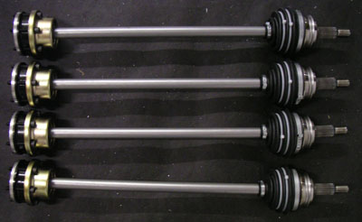
I still need to come up with the rest of the exhaust system - the muffler and the pipes leading to/from it. But that is less critical right now, initial drive could probably be done without a muffler if it came to that. I now can design the oil tank (which sits between the exhaust and the frame, behind the engine) and move forward with plumbing. In other tasks, I need to disassemble and re-seal the rear diff. I think I'll get the fixture from TRE so I could clamp it without damaging the plating. Meanwhile I put together the CV joints and packed them with Redline CV grease. Having learned from the Westie experience where outer CV boots expanded from high RPM and hit surrounding hardware, tearing themselves in the process, I've put zip ties on the outer boots to prevent any 'ballooning' at speed. With 20" rolling diameter tires and 160mph projected top speed those things will be spinning pretty fast. I don't want to have them fail. The inboard boots are different design and aren't an issue.
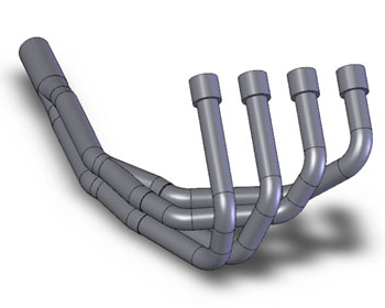
10/16/05 (Updated 10/17/05) Switching from real world to CAD, I decided it was time to model the new exhaust header.
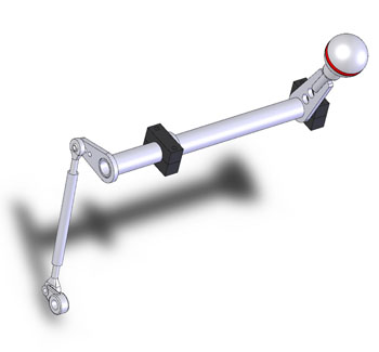
This took a while but the result is fairly accurate - and I learned a couple more things about SolidWorks in the process. Speaking of learning, when I posted the original pictures of the header someone wrote me saying it was made incorrectly - the pairing of cylinders 1-2 and 3-4 does not seem to make intuitive sense. Cylinders 2-3 and 1-4 are 180 degrees out of phase and the 'correct' way would be to pair those. I did some checking and the stock Suzuki header was also the 'incorrect' 1-2 and 3-4 pairing. So are a lot of aftermarket exhausts. Interesting. So I called my fabricator. It turns out that if you do the 'correct' 4-2-1 header, it boosts midrange but kills the top end. Alternatively, doing a 4-1 design boosts top end at the expense of midrange and low end (this is why you'll see some all-out racing exhausts made in 4-1 configuration). The 'incorrect' 4-2-1 header produces the best overall compromise, with good gains throughout the RPM range without killing off any one region. Nothing is ever as it seems :) While messing with SolidWorks I finally got around to designing the shifter mechanism. Due to the layout it turned out very simple, direct and clean (it's highlighted in green in the big picture).
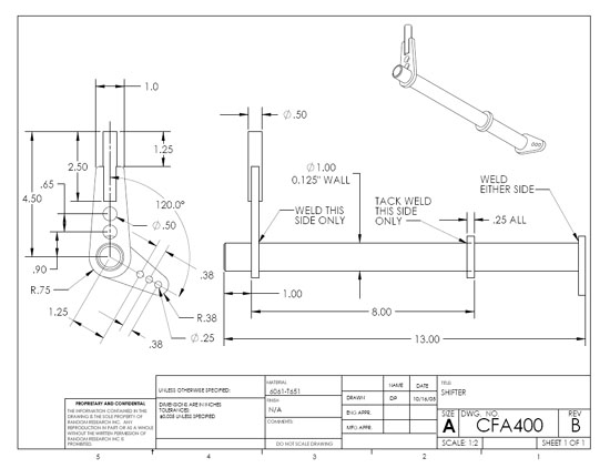
The knob is a MOMO Sphere with red leather band (to match the steering wheel) - I found one online for a good price and ordered it. The shift action is forward for downshift, back for upshift - this is the way I had the Westie set up and it works intuitively for me (I recently drove an Audi which has it backwards and I didn't like that). Now I need to do detail drawings and have it made. After that, throttle pedal and linkage (it's already designed in my head, just have to CAD it). Moving forward, one step at a time. UPDATE: After tweaking ergonomics, doing some stress analysis and checking material availability, the shifter design has evolved some.... It's out for quotes now.
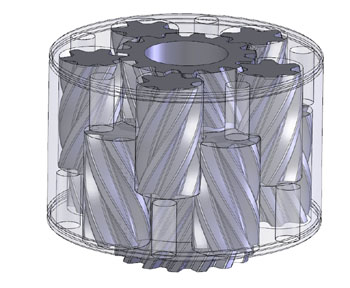
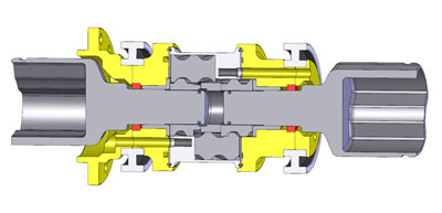
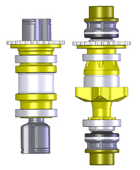
Drawings are always a pain - the challenge is to include enough information to eliminate any ambiguities while minimizing clutter and confusion. I'm only adequate at this, not great by any stretch. At least SolidWorks makes it semi-easy. The 'easy' part being a relative term, of course. But I definitely am glad I don't have to pay a draftsman to do this. 10/22/05 I've been working on the project quite a bit lately, just haven't gotten around to doing an update. The stuff I'm doing for the most part is assembly and debug. For example, I finally took apart and re-sealed the leaking diffs (had to buy a fixture and a spanner nut driver for it but the tools do make it much easier). Putting the front diff back together one of the spring washers slipped and jammed the whole thing solid (illustrating how the locking works! ;) so I had to take it apart again and re-do. Another lesson learned. In the process of doing the diff service I started pondering the function of the Quaife design so after I got home I threw together a quick SolidWorks model using a Quaife I have laying around as the basis.
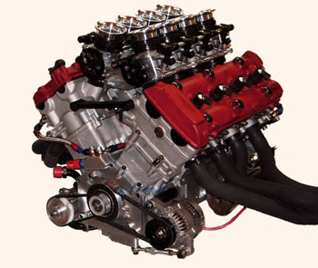
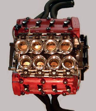
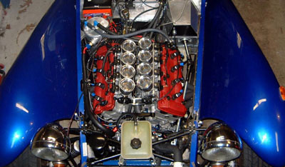
After staring at it for a long time from a variety of angles what has become apparent is that while the diff is in fact reversible, it does have a preferred direction (in which it's preloaded by the spring washers). It would be slightly less effective at locking if driven the other way, though by how much is very hard to quantify, and of course it would still function fine as a diff. This conclusion, along with a number of other considerations (like packaging of the belt drive and heat/brakedust management), is leading me to contemplate moving to conventional outboard brakes for production. The diff-mounted brake is a noble attempt at reducing unsprung weight and simplifying things, and it will probaly work fine in the prototype, but I suspect practicality will dictate going the less exotic route ultimately. From my years of engineering I've learned that a successful development effort has to be pragmatic. On the one hand, a certain amount of design risk needs to be taken (otherwise why bother?), but on the other hand some things will just invariably end up being more trouble than they're worth and it's important to recognize those, accept it and move on - but without giving up too early on ideas that can produce a real advantage. Of course it's too soon to tell for sure but the center-brake deal is starting to show some signs :) At any rate, the prototype will be so equipped and if I change it for subsequent versions then there will be a good opportunity for back-to-back testing. As a quick aside while on the subject of diffs, the stock Quaife that I used for my model weighs 14 lbs, without drive flanges or bearings. With a custom housing I can get it down to around 6 lbs if I use a plated aluminum core (8 lbs if I use steel). Food for thought. Any experts on Nikasil plating out there? So after re-reassembling the diffs I put the halfshafts in and tightened up the wheel spindles so the wheels don't wobble now. Turning the steering wheel in this configuration revealed a flaw - the steering rack bracket flexes. I was in fact warned about this by someone who had experienced a similar problem with the Stiletto rack (due to its inherent mounting scheme) but I thought my approach would be stiff enough. Guess not. Basically the thing needs to be mounted in double-shear unless a very substantial base plate is used. So I designed a simple reinforcement and sent the drawing off to have it made. Should be a straightforward bolt-on deal. Another point of progress is the plumbing. I've decided to go with an off-the-shelf drysump tank mounted just ahead of the engine on the backbone chassis. For cooling, the current idea is somewhat unconventional (and based in part on the results of some racecar testing I observed). Since I have two radiators and each is bigger than the stock Hayabusa one, I'm going to try using just one radiator for water and the other for oil. The oil will be fed to it from the drysump scavenge pump and will go to the tank after the radiator. Therefore it's all low-pressure stuff and the radiator should be able to handle it. It should also be more efficient because the scavenged oil is the hottest it gets so heat exchange is quicker and I can have an ample supply of cool oil in the tank. The stock oil cooler path will be bypassed. On a related subject, I've been having quite a few discussions about racecar design and opportinities for advancement on the current state of the art in DSR (Stohr). This coincides nicely with the evolution of my own car and many of the ideas should be applicable. Considering that I'll most likely be going to outboard brakes I can repackage the suspension to reflect some of this new thinking, opening the way for improved bodywork down the line.... Lots of possibilities. Hopefully this prototype will answer many of the questions and help choose the next direction. I'm just getting started here :) 10/25/05 More progress, some of it just tinkering with stuff, some more conceptual in terms of how I'm going to solve the remaining issues and what I'll be doing for production. It is also gratifying that I'm not the only one moving forward - the development of the V8 that I'll be using is progressing as well. The engine is now running in a Lotus 7 and undergoing testing and development. Detailed information will be available early next year (so don't ask :) but for now here are some pictures:
The motor is based on two Hayabusa top ends joined together. 360hp, 210 lb-ft, about 220 lbs weight. Yes, I already know what I'm going to do for a gearbox and how the whole thing will mount in the car. I'm waiting for CAD files to finalize the details and make sure the production chassis will accommodate this powertrain. I was also thinking that it should make an awesome Elise engine ;) My tinkering with the Quaife model led me to develop a unit that could theoretically be produced. It would use stock internals from a volume-produced Quaife diff, only the housing is custom. The result would be about the same weight and general size as the TRE diffs I'm using now. My design is quite different from the TRE approach. It is a bit less flexible but is somewhat simpler and would hopefully seal better. Worth doing? I don't know yet. Not the highest priority I guess, just something my mind latched onto so I had to take it far enough to see if it's feasible. It is.
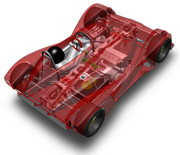
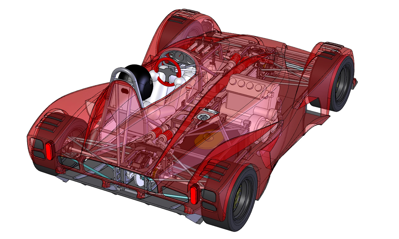
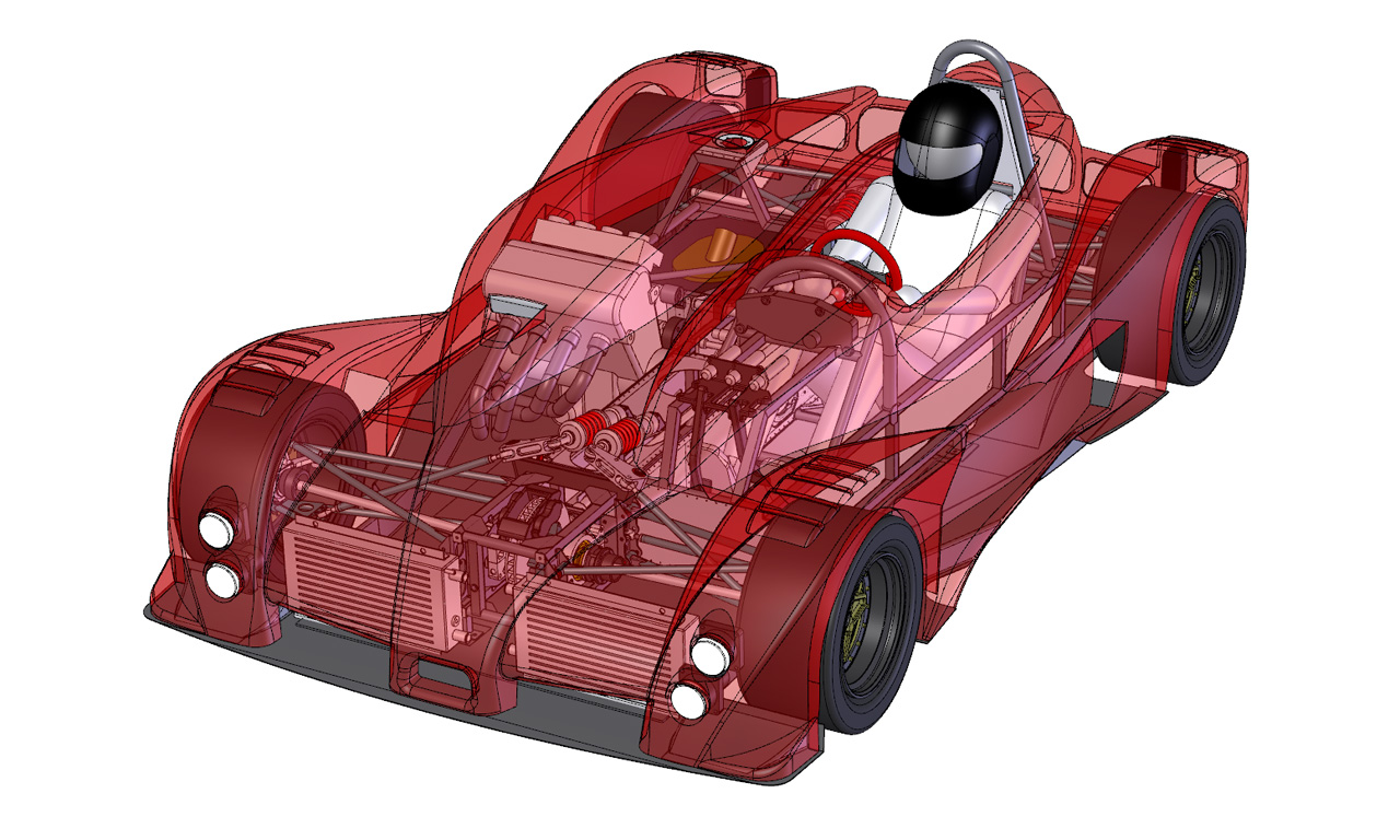
While making pretty pictues with SolidWorks I realised it's been a while since I posted a full transparency view with all the latest bits and pieces in it - so here are a couple. Click for bigger.
In fact, if you want to spin it around in 3D just download this eDrawings file (6M). The viewer can be downloaded for free from SolidWorks website. Next is figuring out what exactly I need to order for the plumbing (and where from), then ordering it. The specific tasks are center diff (have to figure out fill/vent scheme because stock won't work in this orientation), oil system, fuel system (header tank and high-pressure pump mounting and plumbing), cooling system and brakes. That'll keep me busy for a while. In the meantime, just in time for Halloween, a monster will be visiting my garage. But only for a month or so. Details soon :) |